1. PROBLEM DESCRIPTION
Deacon Engineers carried out the design of large, rotating digesters for the treatment of municipal solid waste. The digesters are approximately 65m long and 4.5m in diameter and rotate continuously, at 1 rpm, while processing up to 500 tonnes of waste. Due to the cyclic nature of the loading, careful attention had to be paid to the fatigue design of the digesters. The standard adopted was British Standard 7608:1993 Code of practice for fatigue design and assessment of steel structures (BS 7608).
2. UNIAXIAL & PATH DEPENDANT CYCLE COUNTING
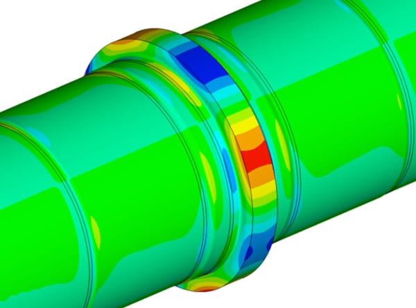
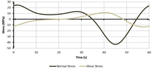
Recent advances in fatigue design methods show that where there exists a significant fluctuating shear stress component, a multi-axial cycle counting technique should be used in order not to over-estimate the calculated fatigue life. Uni-axial cycle counting methods, such as the Rainflow method, can lead to unsafe estimates of fatigue life. Path-dependant cycle counting methods for variable amplitude, multi-axial loading should be employed in order to obtain the best estimate of the fatigue life. In the case of the digesters, the shear stress component was significant in the tyre region, as shown in Figure 1 and Figure 2.
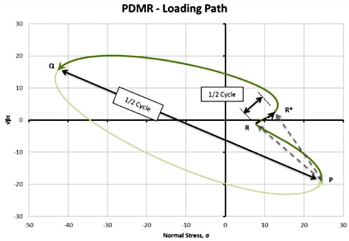
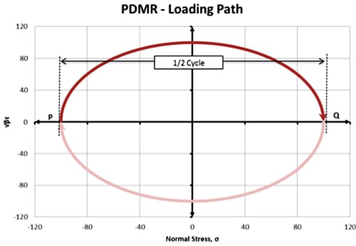
3. SIMPLE PATH DEPENDANT MAXIMUM RANGE (PDMR) EXAMPLE
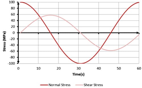
The following graph shows typical out of phase biaxial normal and shear stresses on a circular shaft in tension and torsion. The range of the constant amplitude normal stress is 200MPa.
4. OTHER APPLICATIONS
Typical equipment which is subjected to multi-axial and out of phase loading with significant shear stress components, and which needs to be analysed using the fatigue analysis techniques discussed here, are listed below:
- Kilns
- Mills
- Scrubbers
- Granulators
- Railway axles
- Drive shafts